32 Bit address support #1
Reference in New Issue
Block a user
Delete Branch "%!s()"
Deleting a branch is permanent. Although the deleted branch may continue to exist for a short time before it actually gets removed, it CANNOT be undone in most cases. Continue?
By changing the addressing modes, it is possible to convert the 6502 from using 16 bit addresses to 32 bit addresses. Any instruction which deals with 2-byte addresses is modified to work with 4-byte addresses instead.
The 6502 has 15 addressing modes. Here is how each of them will change:
Overall, there are not too many different changes.
The registers all remain 8 bits, except for the program counter which obviously must be 32 bits.
The vector addresses also change since they are 32 bit now instead of 16 bit.
Backwards compatibility is NOT a requirement. There is NO need to have a 16 bit mode, or be able to run existing 6502 code in any way.
Starting from the top, the first thing that needs to change is state
IND0All
IND0does is go toINDX1, bypassing theINDX0state where the zp address is added with the X register. This state therefore requires no modifications since it will be handled by theINDXnstates.We will revisit this one when we handle the other zero page indirect modes.
second state that needs changed is
ABSncurrently there are 2 states, for loading 2 bytes
ABS0 increments the program counter
The ALU is set to add by default, AI is set to 0 by default, BI is set to DIMUX by default.
ABS1 sets the next address to the combination of DIMUX and the ALU output
So, in order to support 32 bit addresses we need to have 16 more bits of temporary storage. Right now it uses the ALU output register, as well as the input register. We can have an ALU shift register which simple stores the last 2 results of the ALU. In the final state when we jump to the new address, it will do
AB = {DIMUX, ALU_SR[1] ALU_SR[0], ADD}This will be the result of ABS3. ABS0,1,2 will all be the same, just incrementing PC
Actually before we do that, we need to do the vectors so that we can even reset the chip.
We start in state BRK0
This sets the address to the current stack pointer, which will still only be 16 bits. We can hardcode the upper 16 bits to 0.
In BRK0 and BRK1, as well as JSR0 and JSR1, we push the current PC to the stack. We need to add 2 more states so that we can write all 32 bits, instead of just 16
In BRK2 we write the processor status register, so we can just move that back a few cycles
BRK1 and BRK2 increment the address, our stats will do the same
Here is where the vectors are harcoded. We will change these vectors to be at 0xFFFFFFF4, 0xFFFFFFF8, and 0xFFFFFFFC.
The BRK changes are added in
9476c6a0ddNow that we have those, we need to update the JMP state, since it is only waiting 1 cycle for an address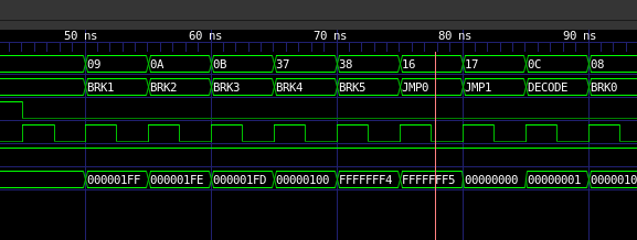
JMP does not really do anything. If we add 2 more JMP0 like states as well as the ALU shift register, this should be trivial.
JMP changes are added in
019b84f41dThis is the Absolute jump
Lets tackle absolute for normal instructions next.
747438a9b6This was pretty simple, we just copy the ABS0 state two more times.
abs,x next.
Looks like we can just copy this state
2 more times
Added abs,x here
cb6cac1245abs,y should also be handled by abs,x add those to the test also
Lets tackle absolute,x indirect.
This is states JMPIXn
Like absx, We can probably just copy this state twice
Ok that is one in
dc339cb725Now for regular indirect. We can just copy JMPI0 twice.
Added in
b31d7490b2Lets do Indirect Indexed, since it is apparently the most common indirection mode.
according to the state listing, here are the steps that we do
How should we make this work with 32 bit addresses?
The first step loads the LSB and sends the ZP index to ALU
the second step reads the MSB and sends the LSB to ALU to add Y
the third step reads
So we need to do a combination of steps 2 and 3. Instead of loading data from the calculated address, we need to read the 3rd and 4th bytes from zero page and add the carry. Only then can we read from the computed address.
Hmm that plan would not work because we need the ALU to be adding the offset, whereas this instruction also uses the ALU to generate the address.
So we need to load 4 bytes from zeropage, which means we need to calculate 4 new addresses, but at the same time we also need to add the Y register to what we are reading. We might need to add another adder just for handling increasing the address.
dfe27d4ec7What I ended up doing was adding another signal which could increment the address bus register. This does mean that there are two 32 bit adders, one for PC and one for address bus, along with the ALU. I think that this is better than the alternative of adding extra registers and taking nearly twice as many cycles
Last one is indexed indirect, which should be easier since we don't have to add to a 32 bit number, only an 8 bit number.
ok it still uses the ALU to increment the ZP pointer, so we can use the same extra adder that we added for the other ZP state.
Done in
2a9af9e9dcWe've added all addressing modes, but not all instructions will be functional. For example, the absolute and absolute,x addressing modes are supported on a bunch of different instructions, we need to make sure that the timings line up for the side effects.
What we probably need to do is test every single instruction in every single addressing mode that it supports.
I think we should have tests for every instruction which has those addressing modes. Also, we need to handle the extra cycles if there is a page crossing. Lets start at the top width ADC
thats gonna be boring. One thing that we definitely need to test is JSR, RTS, BRK, and RTI.
These involve pushing and popping more bytes to/from the stack.
basically we just need 2 more jsr0/jsr1 states, easy as.
What the 6502 does is use the stack pointer as temporary storage for the LSB of the jump target. We need to store 3 bytes instead of 1 though. We use the ALU to decrement the stack pointer while we are writing the current PC and status register to the stack. What we could do instead is read the next 4 bytes and jump to it using the alu output shift register like we do for jump
Hmm we can't use the ALU to both store the stack pointer and also use its shift register to store the target address.
Ah we can swap it back in state JSR4, that will keep it inline since JSR5 will read the second byte of the address.
In terms of cycle count, we have added 4 cycles making JSR take 10 cycles. This is almost double the length, but hey performance was not a goal.
RTS follows a very similar pattern to JSR, except instead of pushing from the stack we read from the stack. This should be a little bit easier too.
we cannot use the ALU to decrease the stack pointer while also using the ALU registers to store the temporary address. What we could do is modify the shift register to take in data from DIMUX instead of just the ALU
when the original cpu pushes the address to the stack, it has already incremented PC once, so if the addresss start at 0x200
JSR LSB MSB, the PC is pointing at MSB when we start writing. This is 1 less than the address we want to jump to. When we are writing 32 bits, we are now 3 less than what we need to jump to. We cannot just keep increaseing PC though becuase that means it will be changing as we are writing to it. We could add 2 more dummy cycles at the end of RTS, or we could make it so that we can add 3 to PC instead of just 1. One requires more area, one requires more cycles. Since area is basically free, lets add the +3
Ah we need to use the alu_sr sel to store dimux into the shift register, so that we can use the alu to decrement the stack pointer
Now we need to implement BRK and RTI. This should be mostly similar to JSR and RTS except that we push and pull the flags register as well.
We basically did BRK earlier when we did reset. RTI now works, but we should test external interrupts though just to make sure they function as expected.
Oh also the branch commands will need to take calculate a 32 bit address instead of 16 bit, so thats potentially 2 more cycles that each one will take.
So it kind of works but WAI increase pc by too many, it should increment PC by 1 put it increments it by 2 instead. WAI is kind of fake, but we can add a state to decode to fix this anyway.
Ok we changed how branch works, so it should mostly work now. With that, I think we have everything mostly functional. Now we can work on modifying cc65 to generate code for our new target.
I think this is ready to merge, works good enough.